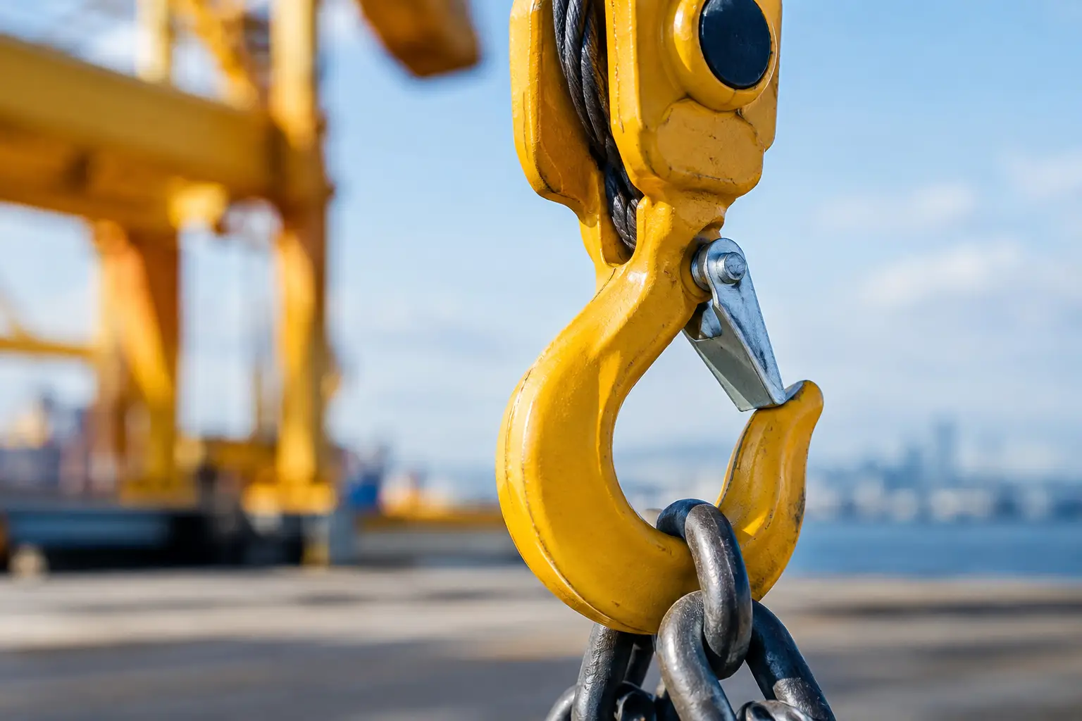
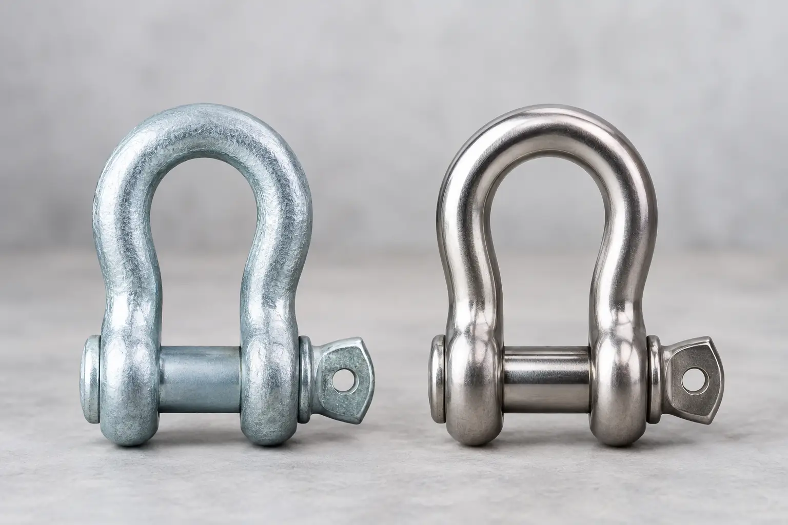
A shackle stamped with a working load limit is not automatically suitable for every lift. Shackle derating rules apply when the load does not act in the direction and configuration for which that shackle was rated. Side loading, angular loading, multi-leg connections, and poor pin alignment can all reduce usable capacity, even when the calculated load appears to be below the marked WLL.
For lifting supervisors, vessel crews, and rigging teams, the practical requirement is straightforward: evaluate the complete connection before the lift starts. A correctly selected, certified shackle can be the right component for a demanding job. The same shackle used outside its manufacturer’s stated conditions can become the weak point in an otherwise sound rigging arrangement.
What a Shackle WLL Actually Covers
The working load limit marked on a shackle normally applies to an in-line, symmetrical load through the body and pin. The load should be centered in the bow, the pin should be fully engaged, and the shackle should not be twisted, forced open, or subject to bending from an incompatible fitting.
This baseline matters because a shackle is not simply a piece of steel with a capacity assigned by size. Its pin, bow geometry, material grade, heat treatment, and design all contribute to its rating. The manufacturer has tested and rated the assembly for specific loading conditions. Once the force moves off center or acts at an angle, stress distribution changes across the bow and pin.
Do not treat the WLL as a breaking-load estimate with spare capacity available for jobsite adjustments. The design factor is already part of the rating. It is not additional capacity that can be used to compensate for an unfavorable rigging configuration.
Shackle Derating Rules Start With the Manufacturer
There is no single derating chart that safely applies to every shackle on the market. Ratings can vary by shackle type, grade, bow shape, pin design, standard, and manufacturer. A screw-pin anchor shackle, bolt-type anchor shackle, and D-shackle may have different limitations even when their nominal WLLs appear similar.
Use the manufacturer’s current technical data for the exact product being deployed. That information should identify whether side loading is permitted, the allowable loading angle, applicable reduction factors, and any restrictions on multiple sling legs. Where documentation is unavailable, unclear, or inconsistent with the lift plan, do not assume a generic factor. Select a configuration with a clear, documented rating or obtain engineering guidance.
This is especially relevant when lifting equipment has been supplied from mixed sources or has been in vessel stores for years. The body marking alone may identify the WLL, but it may not provide the operating limitations needed for an angled connection. Traceable certification and product data are part of the lifting equipment package, not paperwork to be checked after the job.
Side Loading Is Not a Minor Variation
Side loading occurs when the load is applied across the plane of the shackle rather than directly in line with it. Common examples include a shackle joining two sling legs, a connection to pad eyes that do not align with the sling direction, or a shackle used at the head of a bridle arrangement.
Some anchor shackles are specifically designed and rated for limited side loading within stated angles. Others should not be side loaded at all. A D-shackle is generally better suited to in-line loading and is not a substitute for an anchor shackle where multiple connections or angular loading are expected.
Side loading can force the shackle bow to spread or impose bending on the pin. The risk becomes greater when the angle increases, when loading is asymmetrical, or when one sling leg takes more load than expected. A two-leg sling connection may look balanced while the center of gravity, unequal leg lengths, friction, or load movement creates a significant difference in tension between legs.
For this reason, a lift plan should identify the angle at the shackle, not only the sling angle at the load. These are related but not always identical. A shackle connecting a sling to a lifting lug may be correctly aligned at the lug while the shackle at the master link is side loaded.
Multiple Sling Legs Require Capacity Checks at Every Connection
In a multi-leg sling assembly, each leg develops higher tension as the included angle opens. For a symmetrical two-leg lift, leg tension can be estimated as:
`Tension per leg = Total load / (2 × cos θ)`
In this formula, θ is the angle of each sling leg measured from vertical. As the legs move closer to horizontal, tension rises quickly. At the same time, shackles at the master link or lifting points may experience angular loading that requires a separate derating review.
The sling-leg calculation does not establish the shackle capacity by itself. It only identifies the force that the shackle may need to carry. The shackle must then be assessed against its own approved loading condition and applicable reduction factor. Never apply a sling-angle factor and assume the result covers the shackle geometry.
Where three- and four-leg sling sets are used, do not automatically assume all legs share the load equally. Unless a qualified lift design confirms equal load distribution, standard practice may require the load to be assessed on fewer effective legs. The applicable site procedure, governing standard, and lift classification should determine the design approach.
Pin Alignment and Connection Fit Matter
A shackle can be derated by poor connection geometry before the lift begins. The pin should carry the load cleanly and should not be loaded against the thread area, wedged against a lug, or bent by a connection that is too narrow or too wide.
Use compatible components. The eye of a sling, hook, or lifting lug must fit within the shackle without being crowded, point loaded, or forced onto the pin. Multiple components on one shackle pin can create uneven loading and should only be used where the manufacturer permits the arrangement. A larger shackle is not automatically the answer if its pin does not properly match the connection.
The orientation of the pin also matters. For a shackle joining a sling to a lifting lug, the sling eye is commonly placed in the bow and the lug is connected to the pin, provided this arrangement maintains alignment and follows the equipment instructions. The goal is to prevent the pin from rotating, backing out, or seeing unintended bending during the lift.
Screw-pin shackles require particular attention where vibration, load cycling, or movement could rotate the pin. In these conditions, a bolt-type shackle with a secured pin may be the more suitable choice. Selection should follow the duty, not just availability in the rigging store.
Do Not Stack Derating Factors Without a Defined Basis
Complex lifts often combine several limitations: sling angle, side loading, below-the-hook device capacity, pad-eye orientation, environmental conditions, and dynamic effects from vessel motion or crane travel. It can be tempting to apply several percentage reductions to a shackle WLL and accept the resulting figure as a safe working capacity.
That approach can be misleading. Some manufacturer factors are intended for one specific configuration and may not be combined with another factor unless the technical guidance explicitly allows it. Other conditions may prohibit use altogether rather than call for a percentage reduction.
If a lift involves more than one nonstandard loading condition, treat it as an engineered rigging question. Confirm the arrangement with the shackle manufacturer, a competent person, or the project engineer. This is particularly necessary for offshore lifts, lifts over live plant, personnel exposure, critical lifts, and marine operations where motion can introduce dynamic loading.
Inspection Does Not Replace a Configuration Review
Pre-use inspection remains essential, but a shackle that looks serviceable may still be unsuitable for the intended lift. Check the WLL and identification marking, correct pin type, thread condition, bow and pin deformation, cracks, corrosion, unauthorized welding, gouges, and heat damage. Verify that the pin belongs to that shackle and has not been substituted from a similar-looking item.
Remove equipment from service when inspection criteria are not met. Do not straighten a bent shackle, rework threads, weld repairs, or paint over damage to return it to use. Any repair or modification must be controlled by the manufacturer or an authorized competent process, with appropriate recertification where applicable.
Inspection records should sit alongside the lift plan, certificates, and equipment register. For project teams working to tight shutdown or vessel schedules, having the right documentation ready prevents a last-minute substitution that compromises the rigging arrangement.
A Practical Check Before the Lift
Before approving a shackle connection, confirm four points: the actual load in the connection, the direction of loading, the compatibility of every attached component, and the manufacturer’s permitted use for that configuration. Then verify that the shackle is identifiable, certified, inspected, and included in the lift plan.
For urgent work, the safest solution is rarely to make an available shackle fit. It is to source hardware sized and configured for the actual geometry, with load-test certification and documentation that match the job. C&C International can support this process with certified lifting hardware, technical selection, and job-ready rigging configurations for marine and industrial applications.
A shackle is a small component in the lifting system, but its loading condition deserves the same attention given to the crane, sling, and lifting points. When the geometry changes, reassess the rating before the load leaves the ground.