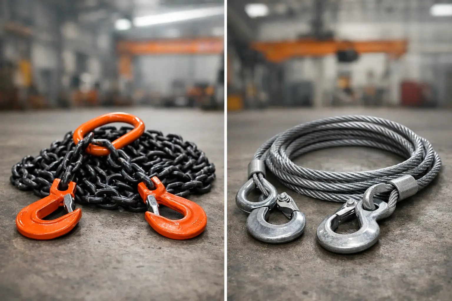
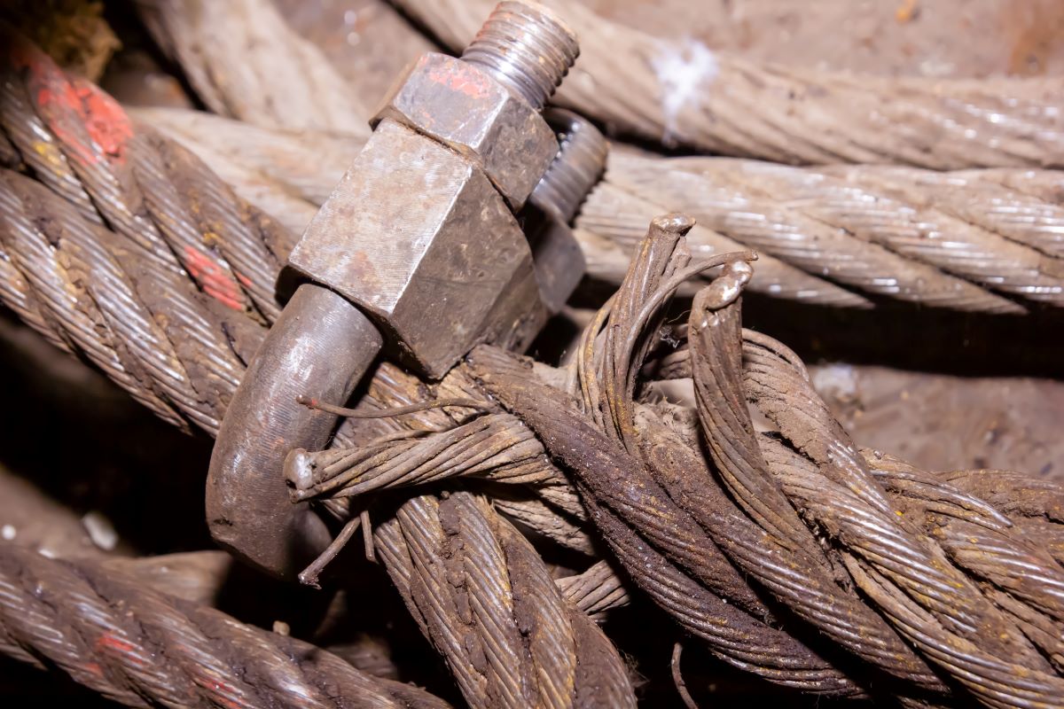
A slack lashing, brace, or guy line can become a safety and schedule problem long before it visibly fails. Turnbuckle tensioning systems provide the controlled, incremental adjustment needed to set and maintain tension in wire-rope, chain, rod, and cable assemblies. For marine, offshore, construction, and industrial work, the right system is not simply a turnbuckle selected from a catalog. It is a compatible, rated assembly with known load paths, sufficient adjustment range, correct end fittings, and inspection records that support safe operation.
Where Turnbuckle Tensioning Systems Fit
Turnbuckles are mechanical tensioning devices. A central body with right-hand and left-hand threads allows tension to be increased or reduced by rotating the body, without disconnecting the assembly. They are commonly used in fixed-length rigging where fine adjustment matters more than frequent repositioning.
Typical applications include wire-rope bracing, antenna and mast guys, architectural tension systems, cargo restraint arrangements, equipment supports, vessel access structures, and selected marine mooring or securing duties. In each case, the turnbuckle must be considered as one component in a complete system. The wire rope, terminals, shackles, chain links, pad eyes, anchor points, and structure all need compatible ratings and geometry.
This distinction matters because a turnbuckle can be physically large yet unsuitable for a particular duty. Thread size, body design, material grade, end configuration, and manufacturer-rated working load limit all affect performance. A mismatch at any connection point can reduce the capacity of the assembly or introduce side loading that the hardware was not designed to carry.
Selecting the Correct Turnbuckle Configuration
The first selection question is not size. It is the application load, including expected static tension, dynamic effects, possible shock loading, environmental exposure, and the required safety factor. A qualified person should establish the design requirement before hardware is specified.
Body type and adjustment range
Open-body turnbuckles make thread engagement easy to inspect and are often practical for general rigging and bracing. Closed-body or pipe-body designs provide more protection to the threads in exposed environments, but they make visual verification of engagement more difficult. Where thread condition and adjustment need frequent checking, access should influence the selection.
Adjustment range must be sufficient for installation and future retensioning. Starting with the turnbuckle nearly fully closed or nearly fully extended leaves little room for correction. A properly planned assembly is normally installed with usable travel available in both directions, while maintaining the manufacturer’s required minimum thread engagement.
End fittings and connection geometry
Jaw, eye, hook, and stud ends serve different connection requirements. Jaw ends are commonly paired with a clevis pin and can provide a direct connection to a lug or pad eye. Eye ends suit shackle connections and certain wire-rope terminations. Hook ends can be useful in limited applications, but they demand positive retention and should not be assumed suitable where load movement, vibration, or critical lifting exposure is present.
Connection geometry deserves the same attention as the turnbuckle body. Pins must fit correctly, shackles must not be point-loaded, and attachment points must be aligned with the load direction. A turnbuckle intended for straight-line tension should not be forced to accommodate angular loading. If the assembly cannot align naturally, a different fitting arrangement or a properly engineered connection may be required.
Material and corrosion resistance
For indoor industrial use, galvanized or painted carbon-steel hardware may be appropriate when it is kept within its rated service conditions. Marine and offshore exposure often calls for higher corrosion resistance, such as hot-dip galvanized hardware or a suitable stainless-steel grade. Material selection depends on the atmosphere, immersion risk, chemical exposure, temperature, and the risk of galvanic corrosion where dissimilar metals meet.
Stainless steel is not automatically the best answer for every saltwater application. Grade, strength, crevice conditions, thread lubrication, and compatibility with adjacent hardware all matter. For critical service, select by documented properties and intended environment rather than appearance alone.
Installation Controls That Prevent Common Failures
Most turnbuckle problems originate in installation, not in the body itself. The assembly should be inspected before tension is applied. Confirm that the body, threads, pins, retaining devices, and end fittings are undamaged; that thread directions are correct; and that the unit has traceable identification where certification is required.
Thread engagement is a primary control. Both threaded ends need to engage the body by at least the manufacturer’s stated minimum. Exposed thread length should be checked on both sides after final adjustment. Uneven engagement may indicate that one end is close to pullout even when the assembly appears secure from a distance.
Turnbuckles should be tensioned gradually and evenly. Do not use improvised extension bars, impact tools, or excessive leverage unless the manufacturer permits the method and the applied force is controlled. Over-tensioning can damage threads, distort end fittings, overload the connected structure, or create stored-energy hazards in wire-rope assemblies.
After adjustment, secure the turnbuckle against unintended rotation. The correct method depends on the body design and application. Lock nuts, safety wire, clips, or purpose-designed locking devices may be used where specified. Safety devices should not replace correct tensioning or adequate thread engagement. They are a secondary measure against loosening from vibration, cyclic loading, or operational contact.
For assemblies carrying significant stored energy, establish an exclusion zone during tensioning. Personnel should remain clear of the line of pull and potential recoil path. This is particularly important with wire rope, tensioned rods, and long bracing runs, where a connection failure can release energy quickly.
Inspection and Maintenance in Service
A turnbuckle that was correctly installed can still degrade through vibration, corrosion, fatigue, accidental impact, and unauthorized adjustment. Inspection frequency should reflect the duty cycle, exposure, consequence of failure, and applicable site procedures. Marine equipment exposed to salt spray, washdown, and weather requires closer attention than hardware in a dry, controlled workshop.
Inspect the body for bending, cracking, thread damage, severe corrosion, and distorted eyes, jaws, or studs. Check pins for wear, elongation, and secure retention. Verify that locking arrangements remain in place and that thread engagement has not changed. Any sudden loss of tension can indicate structural movement, wire-rope settlement, terminal slip, or damage elsewhere in the system.
Remove the equipment from service if there is evidence of deformation, cracked components, damaged threads, unauthorized welding or modification, missing retaining hardware, or unreadable identification where traceability is required. Straightening a bent turnbuckle or chasing damaged threads to return it to use is not an acceptable repair for safety-critical duty.
Lubrication can help protect threads and support smooth adjustment, but the lubricant must suit the environment and material combination. In corrosive service, clean accumulated salt, dirt, and old compound before inspection. A thread that cannot be turned freely may be corroded or overloaded, and forcing it can mask a more serious issue.
Rated Hardware and Documentation Matter
Not every turnbuckle is rated for lifting, personnel-supporting applications, or high-consequence restraint. Product markings and supplier documentation should clearly distinguish rated hardware from general-purpose hardware. Working load limits, proof-test requirements, material certificates, and inspection records must match the actual project requirement.
For lifting-related or engineered rigging arrangements, the applicable design standard, site lifting plan, and competent-person review should govern the selection. A turnbuckle’s working load limit is not a permit to use it in every orientation or every load case. Side loading, shock loading, thread condition, end-fitting geometry, and temperature can all change the result.
For planned shutdowns, vessel work, and specialized installation scopes, an integrated supplier can reduce handover risk by supplying compatible hardware, processing wire rope to specification, completing load testing where required, and providing full documentation. C&C International supports these requirements with configured rigging assemblies, certified testing, PE-endorsed documentation when specified, and onsite installation support for appropriate project scopes.
A Practical Approach to System Planning
Before ordering, define the assembly in operational terms: what is being tensioned, what load will it see, how will it be adjusted, who will inspect it, and what happens if it loses tension? Those answers usually determine the body type, end fittings, material, adjustment range, certification needs, and installation method more reliably than selecting by nominal size alone.
The best turnbuckle system is one that can be installed with clear thread engagement, tensioned without improvisation, secured against rotation, and inspected by the people responsible for the work. When the assembly is treated as a controlled load path rather than a simple piece of hardware, it becomes easier to protect both the crew and the schedule.